
INTRODUCTION
Eccentric-high-pressure-centrifugal-comminution (eHPCC™) was conceived in 2013 (Patents pending) and has potential to eliminate the in-efficiencies and complexity of conventional crushing and or tumbling mill circuits. During the development and testing phase eHPCC™ demonstrated improved energy efficiency and sustainability offsets.
eHPCC™ will compliment any upstream feed source, be it run-of-mine (ROM), primary crushed rock, or any other conventional comminution stream such as tumbling mill oversize. A conventional primary crusher or another novel-emerging technology, Conjugate Anvil-Hammer Mill (CAHM) (Nordell and Potapov, 2011), receiving ROM, will be a complimentary open-circuit feed to eHPCC™ for very high throughput flow-sheets.
eHPCC™ may compliment downstream process requirements through selective mineral liberation. Selective mineral liberation is entirely feasible as the ore is comminuted upon itself (autogenously) in the high pressure zone caused by the synchronous rotating components.
This machine has demonstrated to receive lump ore and comminute the ore within a dry, media free environment to approximately 80% passing 120 µm. The feed can be choke-fed or dribble-fed dry with internal classification of liberated minerals as soon as they are produced. This promotes the concept of selective mineral liberation in an open-circuit inert comminution environment. The feed size will scale up with eHPCC™.
The energy efficiency of eHPCC™ has been compared to full-scale conventional mills in the laboratory and has been shown to be 15% more energy efficient (Roper, 2015). The energy efficiency at the laboratory scale takes into consideration the benefit arising from eliminating embodied-free-energy associated with not having to use steel grinding media. Laboratory tests tend to have high motor in-efficiencies, so these reported scale up energy benefits are expected to improve (Roper, 2015).
In addition to the physical testing of eHPCC™ in the laboratory, modern discrete element modelling (DEM) via Rocky Inc. software is improving understanding of the breakage mechanism and process within the grinding chamber.
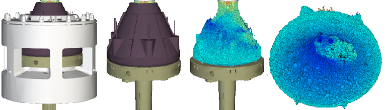
Figure 1 – DEM snapshots of eHPCC™ grinding chamber being charged
eHPCC™ DESIGN PHILOSOPHY
eHPCC™ utilises the mechanism of low-velocity particle-bed breakage; similar to that of vertical-roller mill and high-pressure-grinding-roll (HPGR) technology whose geometries are schematically depicted in figure 2.
eHPCC™ is an evolution of the same, except the opposing surfaces (or rolls) rotate around the same axes, which are parallel to each other, vertical, and selectively offset depicted in figure 3.
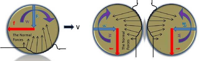
Figure 2 – Schematic geometries of vertical roller mill (left) and HPGR (right) - horizontal side view
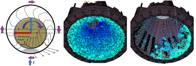
Figure 3 – Schematic of eHPCC™ (left), eccentric-particle-bed (middle) and particle fracture sites (right)
The notable differences in the geometry of eHPCC™, shown in figure 3 (left) as compared against figure 2, are: a) the angle between the tangents of each rolling surface (otherwise known as nip-angle) never exceed nominally 5 degrees; and b) the minimum distance between rolling surfaces exceed the top size of particles entering the machine. The benefits in favour of eHPCC™ are that of enhanced engagement of compressive forces normal to the rolling surfaces (minimizing motion of particles on the roll surface in the nip zone; minimizing skiving and wear) and tolerance of tramp metal inside the machine (the tramp metal never bridges the gap between rolling surfaces; and will aid comminution). The DEM modelling images in figure 3 (middle and right) show the result from rotating the particles and machine elements in sync 1/3 of a turn around their axes; the high pressure zone is on the right of the axes.
View a DEM modelling video demonstrating the mechanism of comminution (produced used ROCKY, by Dr Mike Daniel, CMD Consulting PTY Ltd)
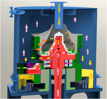
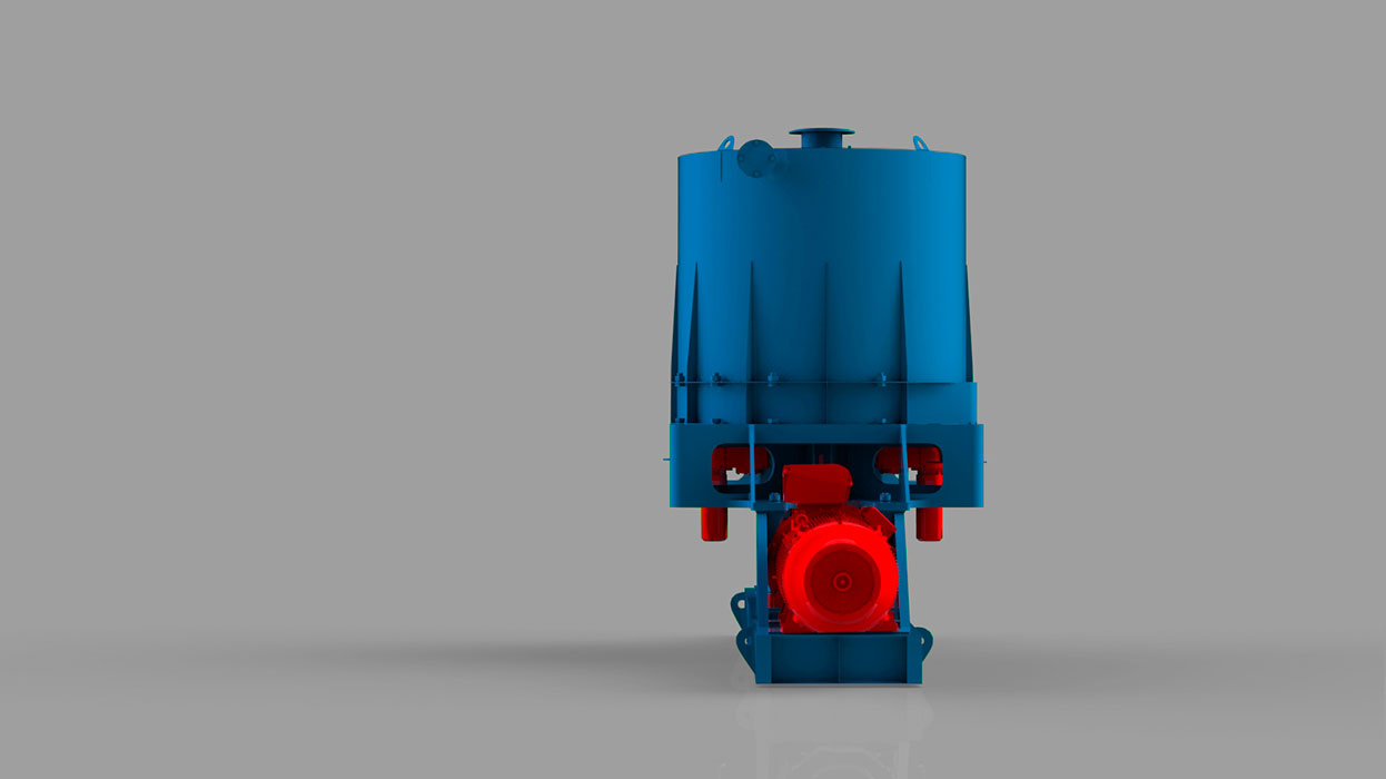
Figure 4 – Sectional view of eHPCC™
eHPCC™ synergises high-pressure-rolling-surfaces with high-intensity-attrition in a continuous sinusoidal action. The fluid-flow dynamics within the eHPCC™, and its capability of selectively retaining oversize particles, enables discrete classification. This is enhanced by optional counter-flow sweeping of product particles from the grinding chamber with process fluid via the shaft (Roper, 2015).
A pressure gradient from inside to outside the grinding chamber establishes product flow. With air this is established using a dust extraction system drawing air from the outer housing, and with water this is achieved by centrifugal force (similar to an impeller). This is partially demonstrated in figure 4 (the process fluid in this case is gas; note the colour of fluid versus that of particles). Feed particles enter by gravity through the top feed chute, air is drawn from the top of the housing, and product falls to the bottom.
We have designed eHPCC™ with intent of eliminating the time-consuming, obscure, hazardous, lifting, handling and fastening practices used to re-line conventional equipment (I.e., horizontally in and out of the confined space of tumbling-mills). Figure 5 presents a story-board of eHPCC™ design philosophy adopted so as to remove confined space, minimise the number of lifts and time to achieve a grinding-chamber re-line. Note: the rotatable-spare grinding-element-assembly (complete with the highest loaded bearings in the machine), and the vertical lifting method.
This can be viewed in the following video. Note the three vertical lifts.
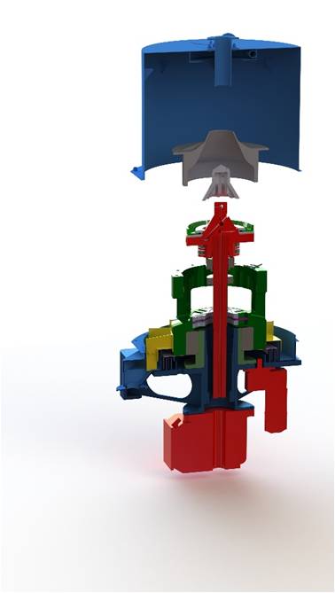
Figure 5 – Story-board of eHPCC™ reline - showing liner change design philosophy
Let us consider the discharge-gap and/or dynamic-seal at the bottom of the grinding chamber, shown in figure 6 (at relative rotational positions 0°, 180°, and 360°). The outer/upper frustum liner oscillates relative to the inner/lower frustum liner as they rotate around their static offset axes. The distance between the rolling frustum surfaces reduces on one side and increases on the other side of the axes. The inner and outer liners oscillate in the radial direction, parallel and in the opposite direction to each other. There is no relative movement in the axial-direction.
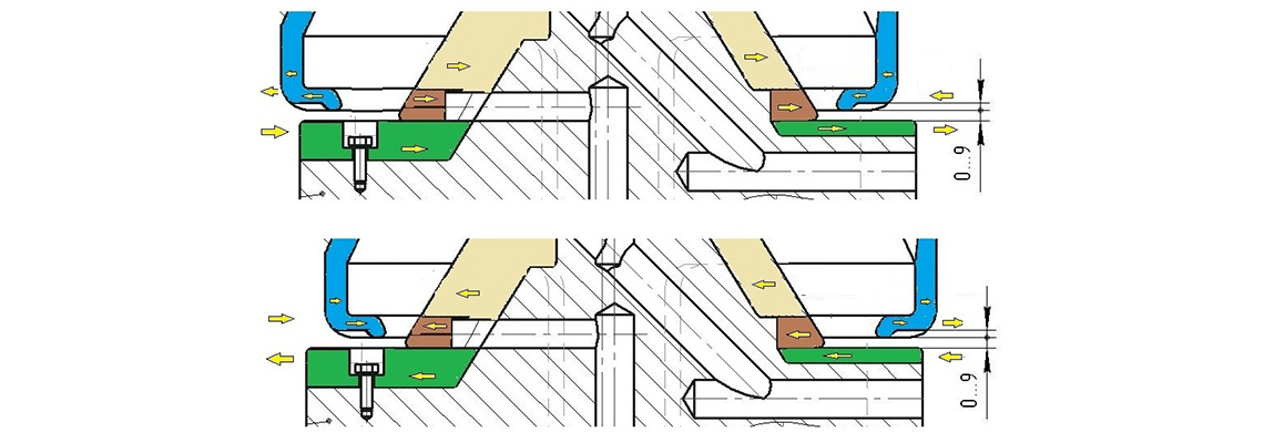
Figure 6 – Sectional-views of liners – shown eccentric
With regard to the discharge gap (figure 6), product particles small enough to have exited the bottom of the grinding chamber will free-flow (by centrifugal force) or roll between the upper and lower surfaces (aided by process fluid). The maximum relative velocity between the liners is 0.5 m/s for our proof of concept machine, and reduces with larger machine sizes.
eHPCC™ CAPABILITIES
Feed Capabilities
eHPCC™ comminuted all feed-material that arrived into its grinding chamber, that being wet, dry, hard or soft. The exceptions and/or limitations of feed were:
Feed Size
The following feed size limitations were observed (note: they scale-up linearly):
- Feed chute dimensions: We designed our proof-of-concept eHPCC™ grinding-chamber with intent of f(100) 30 mm. Irrespective, our feed chute inside-diameter was 62 mm; hence we experienced free-flow feed into eHPCC™with f(100) less than nominally 20 mm. This agrees with the industry rule-of-thumb for free-flow of material through chute openings (I.e., the largest particle-size shall be less than 1/3 of the smallest opening size, or visa-versa; 62 mm / 3).
- The minimum distance between grinding-chamber rolling-surfaces (“minimum roll gap”) dictates the tolerable size of tramp metal; this also dictates the f(100). Our proof of concept machine had a minimum roll gap of 18 mm; eHPCC™ tolerated steel grinding-media with diameter 18 mm (note: it did not tolerate a bed of 18mm grinding media; this is discussed further here below).
- The maximum grinding media size, for deliberate semi-autogenous grinding (a bed of grinding media) is dictated by the same industry rule-of-thumb for free-flow of material (I.e. the smallest roll-gap is 18 mm, therefore the largest grinding media size for semi-autogenous grinding was 6 mm; 18 mm / 3)
Wet or Dry
eHPCC™ comminutes all material that is either hydrated (wet) or dry and hard or soft.
However agglomeration will occur in the event water is added with a dry feed (hydration).
Product Size Capabilities
The following certain conclusion have been drawn with respect to product size distribution:
- Particles are retained inside the grinding-chamber until the desired product size is achieved;
-
Product particle size distribution (PSD) is influenced by:
- Rotational speed (note: there is evidently an optimum speed for classification); and
- Wet or dry comminution (note: dry has much more discrete classification than wet).
-
Grinding media (versus not using grinding media):
- does not significantly improve particle size reduction ratio; but
- does improve rate of throughput.
- Secondary classification is achievable inside the outer-housing by drawing air from the top of the housing (dust extraction).
- When using open discharge gap (as opposed to the dynamic seal), the product p80 is similar to the gap.
Liberation Capabilities
Repetitive sinusoidal particle-bed compression/fluidization (cycle) is shown in figure 7. Softer species of feed (yellow) fail under compression preferentially due to the harder species (black). Harder species remain intact and concentrate at the lower outer circumference of the grinding chamber (centrifugal acceleration will cause them to displace smaller species). The concentration of harder larger species in the grinding chamber enhance comminution as an alternate to grinding media. Machine variables offer ability to selectively/preferentially liberate minerals, minimize energy and enrich/deplete product streams. Figure 8 shows larger harder quartz particles remaining intact, whilst softer minerals reduced in size and separated via fully integrated secondary air classification (open-circuit). This phenomenon with gold-ore measured, analysed, discussed and published in the IMPC 2020 technical paper (downloadable from this website).
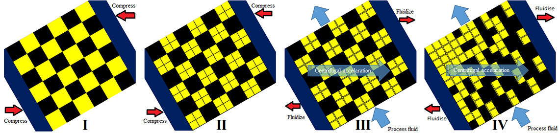
Figure 7 – eHPCC™ particle-bed breakage and liberation cycle
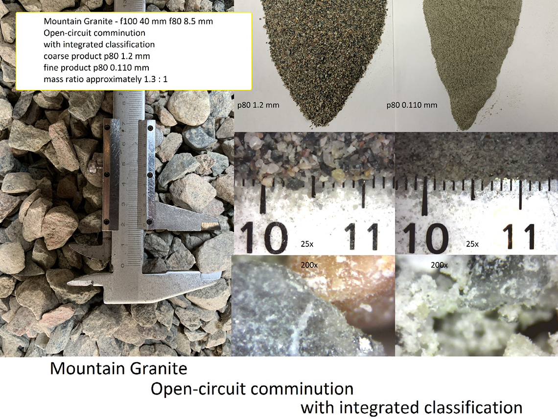
Figure 8 – mountain-granite
Energy Consumption and Sustainability Capabilities
The mechanical properties of feed particles affect the specific energy demand of eHPCC™. eHPCC™ specific energy consumption was compared against that of a conventional-comminution-circuit (Roper, 2015 ). The following conclusions were drawn:
- The absorbed power intensity achievable in eHPCC™ grinding chamber was 4 MW/m3 (4 kW/l) as compared to nominally 21 kW/m3 for the conventional circuit;
- eHPCC™ operated choke-fed, open-circuit, dry and without grinding media as compared to the closed-circuit, wet, steel-grinding-media-consuming conventional-circuit; 15% less embodied-free-energy consumption was measured and determined; and
- eHPCC™ operated with a comparably inert comminution environment.
Financial Capabilities
A discounted average cost comparison of eHPCC™ against a conventional 20 tph copper-sulphide ball mill grinding circuit concludes eHPCC™, in lieu of the conventional circuit, will result in capital cost savings of 44%, operating cost savings in the order 24% and IRR of 70% (in lieu of the base case conventional circuit IRR of 15%) (Borissenko, V., Roper, L., 2015 ).
These cost benefits are achieved by: elimination of grinding media, high-intensity-high-pressure comminution that improves the unit energy consumption, reduced capital costs of auxiliary equipment (elimination of cyclones, and cyclone feed pumps, etc.), and an open-circuit with no recirculating load (Borissenko, V., Roper, L., 2015) .
Scale-up Capabilities
The scale-up capabilities known to be certain are feed size and throughput. Feed size will scale-up in a linear manner with the machine size; and throughput will scale-up with a function involving an exponent of 3 (for volume). The rotational speed will reduce during scale-up by another function catering for the need to limit centrifugal-acceleration on the particles (as the grinding chamber radius increases).
Refer to the webpage dedicated to eHPCC™ selection.